Page 2 of 2
Posted: Thu Jan 21, 2010 7:36 pm
by OldFoo
If you have a Capcom I/O and a Naomi Sun psu, you power the Capcom I/O through the Jamma psu. The Naomi is then powered by the Sun psu. You DO NOT connect the Capcom I/O power to the Naomi. This would probably cause the burn out you mentioned.
Posted: Wed Feb 24, 2010 6:10 am
by OldFoo
so i have a jamma cabinet....
i have the naomi 1 main board and the capcom i/o with a cartridge in there, hooked up to the main power supply just fine and it works
but im trying to get a GD rom in there now....
i have the sun power supply handy, the scsi cable and the power splitter cable....
how do i hook these all up? like where does the black/white cable coming out of the SUN power supply go? where do the 6 pin and 8 pin connectors from the main Naomi board lead to exactly? and how exactly does the power connect from the gd rom to....?
i read the guide and it's pretty helpful but just wanna make sure i don't blow this up!
Posted: Sun Mar 07, 2010 6:56 am
by OldFoo
Hello everyone,
I have a question to propose.
There are no manuals on the jvs i / o? to know all the pinout?
Another question ...
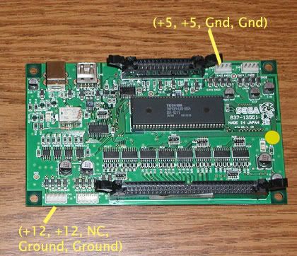
the 2 connectors 4-pin (5volt)
5 pin connectors and the 2 (12volt) are in and out? left right? or are bridges?
very thanks
Posted: Mon Mar 08, 2010 12:58 am
by OldFoo
Andy has the pinout on his site.
click here.
Posted: Sat Jul 30, 2011 8:16 pm
by OldFoo
Can this get stickied please?
Posted: Sat Sep 24, 2011 5:04 am
by OldFoo
Thanks for the info, very helpful since im a total noob at this