Virtua Golf CP problems
-
OldFoo
grantspain wrote:I have a golf kit at work,I will check it out for you
Thanks a lot, but now I got it working. :smt005
Yep, it was about the pinout. Andy, you meant the Golf I/O when you asked this:
AndyGeezer wrote:The other I/O is getting +5v?? does it have the red lights on??
I thought you meant the JVS I/O. But now I took a hard look at the Universal pinouts from the tech section here, and placed the wires to the best of my knowledge, and it worked. Button wires in the wrong places resulted in nothing more than non-working buttons, but I guess the missing +5V was what made the whole thing non-working.
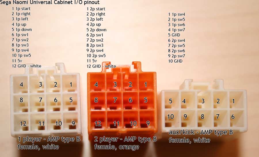
Thanks for the help. Well, now that I've got it sorted out, here's the correct order of the wires: (looking at the cabinet's socket from the front, from the direction of the wires)
http://kirurg.org/arcade/img/sega-cp-cabinet-pinout.jpg
4 . 3 . 2 . 1
8 . 7 . 6 . 5
12 11 10 9
1: Start Button
2: Moves Player Right-button
3: Moves Player Left-button
4: Upper Camera button
5: Lower Camera button
6: -
7: -
8: -
9: -
10: -
11: +5V, connects to the Trackball I/O
12: Ground (Second wires from the buttons)
-
OldFoo
Sorry for reviving an old topic but I got to ask something. Got a Virtua Golf Panel without wiring here and got to ask - okay, obviously the trackball I/O gets its 5V from pin11 of the Amp connector. But what about ground? Is the connector's ground pin12 used for this as well? I mean, wouldn't you get 5V through the buttons if you'd press them? Sorry for the dumb question but it's late and the suzo website is offline - so no manual. Only go the US manuals and pinouts and they use a separate 5V feed...
-
OldFoo
Akuma wrote:Sorry for reviving an old topic but I got to ask something. Got a Virtua Golf Panel without wiring here and got to ask - okay, obviously the trackball I/O gets its 5V from pin11 of the Amp connector. But what about ground? Is the connector's ground pin12 used for this as well? I mean, wouldn't you get 5V through the buttons if you'd press them? Sorry for the dumb question but it's late and the suzo website is offline - so no manual. Only go the US manuals and pinouts and they use a separate 5V feed...
The GND is split from pin 12.
And no you wouldn't get +5V if you press the buttons..