Can anyone take a picture of how this is connected?
I'm sure that the small connector goes with the GD rom drive, but after that, I'm a little unsure.
Does one connect to the motherboard and the other to the Capcom I/O?
That doesn't seem right though - as I've been told an external PSU is needed for the GD rom drive.
Being visual, I've looked for good pictures of a complete setup, but the pictures that I can find on this site either don't show a complete connection (just the parts), or only partial connections.
If anyone has a few minutes to post some pics of a completely wired setup (to an actual cabinet) - I think that would help a lot of us "noobs" out.
Thanks in advance!
Steve
Connection question - power cable splitter
-
OldFoo
Serveral times (in fact, every time you reference it.)
However, there are two things that the picture does not show:
1. What does the PSU connect to on both ends?
If you're just using a Naomi 1 mobo without the GD rom drive, it's easy. The power comes from the JAMMA harness, and there's one power connection - the Capcom I/O board to the Naomi mobo.
However, by adding the GD rom drive, which requires the extra PSU, it's unclear in those pictures what connects to what.
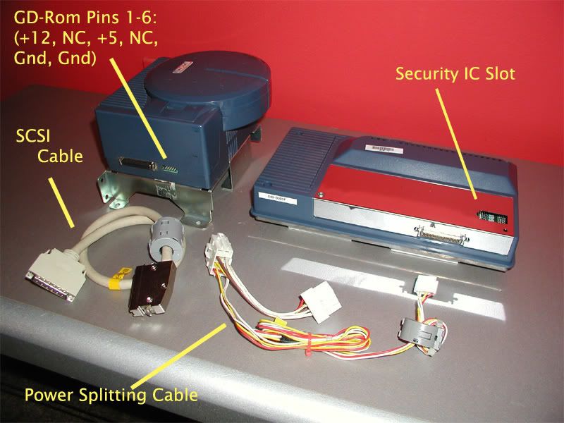
There are three connectors coming from one side of the PSU, and another from the other side. To complicate things, you need the power splitter cable to connect to the GD rom.
It's impossible to tell what connects to what in the picture.
Most importantly, what does the other (single) connector on the PSU connect to? I'm assuming an external power source.
2. Does the Capcom I/O connect directly to the mobo like it does without the GD rom system, as it does with the GD rom system & power splitter cable?
Again, the picture doesn't show.
I'm pretty resourceful, but these pictures simply aren't very helpful at this point.
-
OldFoo
OK,
I'm assuming you have the SUN PSU, and a Capcom I/O
On the PSU, you will have 4 connectors.
1) 1 3pin connector, with 2 wires (Black & White) This is the 110V AC in
2&3) 1 6pin JST connector & 1 8pin JST connector - These supply power to the Naomi Mobo.
4) 1 6pin AMP connector - Used to power things like the Sega JVS I/O & other cab bits (Coin validator etc)
OK, I'm going to make a large assumption here, and presume you got the power cable for the GD-ROM drive (It has 2 JST connectors - One male & one female - and a single 5 (or 6) pin NH connector which plugs into the GD-ROM)
The power cable from the Capcom I/O is only needed if you don't have a 3.3v supply. Basically all it does is take the voltages from the JAMMA connector (so from the JAMMA PSU in a cab) and output the 3, 5 & 12V supplies the Naomi needs.
For your setup, connect the SUN PSU to the Naomi Mobo, making sure you plug in the GD power cable in the loop.
Connect the GD power cable connector to the GD-ROM.
Connect the DIMM to the mobo & the cable between the DIMM & GD.
Connect the Capcom I/O up with the VGA, Audio & USB cables (ONLY)
Connect Capcom I/O to your JAMMA cab.
Turn on power to SUN PSU
Turn on JAMMA cab.
That should be it.
If you are confused, or worried, then take a picture of everything you have & I can talk you through it.
(Sorry for the text only, all my kit is 10K miles away)
-
OldFoo
-
OldFoo
thank you, i have the same question to ask, but in my case i just have a naomi 1 mobo, a capcom I/O and NO SEGA PSU, only the jamma PSU from the cabinet... so, to power a GD Rom, can i use another PSU, like one coming from an old PC, and then modify the wires in the way that i can provvide 3,3 & 5 & 12 V to the GD ROM?
Does the GD ROM neccessary must be connected to the Naomi with power cables, if i use a separate PSU?
And another question (maybe stupid): when i power on the system, the mobo and the GD ROM must be powered at the same time, or if there is a delay (example first mobo and then GD ROM) there will be a problem?
Thank you for your attention and sorry for my bad english again...
-
OldFoo
dj_johnnyg wrote:OK,
I'm assuming you have the SUN PSU, and a Capcom I/O
On the PSU, you will have 4 connectors.
1) 1 3pin connector, with 2 wires (Black & White) This is the 110V AC in
2&3) 1 6pin JST connector & 1 8pin JST connector - These supply power to the Naomi Mobo.
4) 1 6pin AMP connector - Used to power things like the Sega JVS I/O & other cab bits (Coin validator etc)
OK, I'm going to make a large assumption here, and presume you got the power cable for the GD-ROM drive (It has 2 JST connectors - One male & one female - and a single 5 (or 6) pin NH connector which plugs into the GD-ROM)
The power cable from the Capcom I/O is only needed if you don't have a 3.3v supply. Basically all it does is take the voltages from the JAMMA connector (so from the JAMMA PSU in a cab) and output the 3, 5 & 12V supplies the Naomi needs.
For your setup, connect the SUN PSU to the Naomi Mobo, making sure you plug in the GD power cable in the loop.
Connect the GD power cable connector to the GD-ROM.
Connect the DIMM to the mobo & the cable between the DIMM & GD.
Connect the Capcom I/O up with the VGA, Audio & USB cables (ONLY)
Connect Capcom I/O to your JAMMA cab.
Turn on power to SUN PSU
Turn on JAMMA cab.
That should be it.
If you are confused, or worried, then take a picture of everything you have & I can talk you through it.
(Sorry for the text only, all my kit is 10K miles away)
Thank you for your reply - this has been more helpful than some others.
I believe that I understand:
Power split cable 8 pin connects to PSU on one side, Naomi mobo on the other.
Small split cable connection to GD rom drive.
Capcom I/O no longer in the power loop, just Jamma on one side, usb, vga and audio on the other.
My only questions at this point are:
1. What does the 6pin JST connector from the PSU connect to? Anything?
2. What does the 3pin connector (as you've identified that is the 110V AC in) connect to in my cabinet?
Thanks again,
Steve
-
OldFoo
-
OldFoo
Okay.
Here's the setup I've been using:
Jamma harness to Capcom I/O
Audio/USB/8-pin JST/VGA from Capcom I/O to Naomi mobo
Simple.
However, now that I'm integrating the GD rom/DIMM/SCSI, I'll be introducing my SUN PSU, to supply the extra power for the GD rom drive.
Based on your info above, please let me know if this is correct:
Jamma harness to Capcom I/O
Audio/USB/VGA from Capcom I/O to Naomi mobo
8-pin JST from Naomi mobo to SUN PSU female 8-pin JST
6-pin GD rom power cable to GD rom drive
3-pin connector (black & white) on other side of SUN PSU connects to cable (black/white/green) that connects to power transformer (might be wrong on the term) inside the cabinet. This connects to the wall outlet.
What I don't know at this point is what you said about the 6-pin JST.
Do I have to get a 6-pin JST cable to connect the SUN PSU to the naomi mobo?
Is this necessary, or only if you use a Sega JAMMA I/O?
Thanks again,
Steve
-
OldFoo
Hey- hooking up the Naomi GDRom is super-easy. Just make sure to do the following:
Naomi RCA Cables (red and white) to capcom I/O
Naomi USB JVS Cable to capcom I/O
Jamma edge harness to capcom I/O edge connector
Square JST power plugs from Sun PSU to Naomi power plugs
SCSI Cable from Dimm to GDRom
Sun PSU AC power to ac outlet (White/Black = neutral/hot, green = earth ground)
Not sure on your GDRom cable, but there are two types. Both should be compatible with your Sun PSU (assuming its not hacked).
If you have the splitter cable, plug the two square JST power plugs from the Sun PSU into the splitter, then splitter to Naomi. You should be left with one single row JST power connector for the GDRom
If you have the GDRom Power Cable (not splitter), you plug that directly into the female connector coming off of the sun PSU. Its the middle connector pictured below, if I'm not clear in the description.
http://www.sega-naomi.com/pics/segapsu.jpg
Assuming your sun PSU is un-hacked, everything should be plug and play.
Hope that helps!
Bill