Page 1 of 2
Sega Naomi i/o converter PINOUT
Posted: Tue Nov 17, 2009 2:55 pm
by OldFoo
Hi all,
i'm looking for complete pinout for sega naomi i/o converter ,
i have to know all jamma fingerboard assignements ,
in particular if i/o support service and test button,
and how many buttons for each player does it support,
thanks in advice
francesco
Posted: Tue Nov 17, 2009 3:07 pm
by OldFoo
Do you mean the Sega JVS I/O? (Looks like this):
A pinout of that can be found at
http://triplemoonstar.brinkster.net/seg ... ockid=1718
Or if you mean the official Sega I/O with the Jamma connector on it,
http://triplemoonstar.brinkster.net/seg ... ockid=1854
Posted: Tue Nov 17, 2009 3:15 pm
by OldFoo
ok thank you very much,
the jamma version was the one i looking for,
do you know if test and service button on jamma fingerboard are used
as the buttons present on naomi console (used for setting up & test)?
do you know i f i can give power to the i/o board directly from the jamma connector pins?
thanks again
francesco
Posted: Tue Nov 17, 2009 6:13 pm
by OldFoo
The pinout for the Jamma I/O is nearly the same as that of standard jamma. Take a look here--->
Naomi Universal Wiring Diagram<-- from this site's main page. :smt024
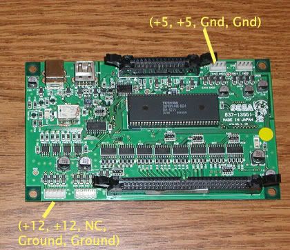
PLEASE NOTE- You can connect power through the Jamma edge or the pin header at the top-left of the board, but NOT both at the same time. :smt018
Posted: Tue Nov 17, 2009 10:03 pm
by OldFoo
Test and Service are the same on both the motherboard and on the Jamma connector, except the service on the Jamma connector also gives a credit (just like most other arcade boads).
Also, just to note: buttons 4 and 5 for each player are also on the Jamma connector (which is not the standard). You only need to hook up 6 (and possibly 7 and / or 8 if your game needs it) on that other connector.
Posted: Tue Nov 17, 2009 11:45 pm
by OldFoo
romshark wrote:Test and Service are the same on both the motherboard and on the Jamma connector, except the service on the Jamma connector also gives a credit (just like most other arcade boads).
Also, just to note: buttons 4 and 5 for each player are also on the Jamma connector (which is not the standard). You only need to hook up 6 (and possibly 7 and / or 8 if your game needs it) on that other connector.
romshark ... I have a Sega i/o jamma converter... It?s working fine on button 1, 2, 3, 4, 5 (directy hookup on jamma) but button 6 (pin 4) on another connector on sega converter not work! I get only wire connected on pin 4 to gabinet painel. The Ground (GND) is same (from jamma) for all buttons. You (or anyone) can help-me?
thanks Alex
Posted: Wed Nov 18, 2009 1:22 am
by OldFoo
Cobr4a wrote:I have a Sega I/o jamma converter... It?s working fine on button 1, 2, 3, 4, 5 (directy hookup on jamma) but button 6 (pin 4) on another connector on sega converter not work! I get only wire connected on pin 4 to gabinet painel. The Ground (GND) is same (from jamma) for all buttons. You (or anyone) can help-me?
thanks Alex
You need to set the jumper to the correct position (A) or button 6 won't work:

Posted: Wed Nov 18, 2009 11:49 pm
by OldFoo
MKL wrote:Cobr4a wrote:I have a Sega I/o jamma converter... It?s working fine on button 1, 2, 3, 4, 5 (directy hookup on jamma) but button 6 (pin 4) on another connector on sega converter not work! I get only wire connected on pin 4 to gabinet painel. The Ground (GND) is same (from jamma) for all buttons. You (or anyone) can help-me?
thanks Alex
You need to set the jumper to the correct position (A) or button 6 won't work:
MKL thanks for you help and picture... the jumper setting is already ok.
Posted: Thu Nov 19, 2009 1:17 pm
by OldFoo
What input exactly are we talking about, P1 6? Do the other inputs on the 14-pin connector work in the input test screen? Measure the resistence to ground of the faulty one and compare it to that of the other inputs on the same connector. It could be a bad P181 transistor. In that case you could replace it with one from the unused input lines.
Posted: Thu Nov 19, 2009 4:00 pm
by OldFoo
MKL wrote:You need to set the jumper to the correct position (A) or button 6 won't work:
According to the
Universal Wiring Diagram I posted to help with this question, you would need to put the jumper in the 2-3 position (Or as the above illustration shows, position 'B').
@Cobr4a:
If you didn't know this already, I've made the wiring diagram a click-able link so the PDF can be downloaded.
