Page 1 of 1
6 Buttons for Player 2 don?t work-- help
Posted: Mon May 03, 2010 9:11 am
by OldFoo
Hi, I have a Sega Naomi Uni Cab. I t was delivered with 3 buttons for each player. I?ve decided to change the control panel to a 2p6b panel. I?ve bought the following cable for adding the missing 3 buttons for each player :
http://www.giz10p.co.uk/Cabinet-Parts/W ... od_85.html
It all works fine for player one (all 6 buttons work) but for player 2 the additional 3 buttons aren?t working (the cable is wired for Naomi). Is there a dip switch or something which I have forgotten to change? Can anybody help me?
MFG FLO
Posted: Mon May 03, 2010 10:54 am
by OldFoo
Your JVS I/O might be knackered if your all wired up correctly and all your buttons are AOK
Posted: Wed May 05, 2010 4:22 pm
by OldFoo
I think my JVS I/O is OK. All six buttons for player one are working now. For player 2 four buttons are working. Can anybody help me? Why does only one button for player 2 (from the kick harness) work?
Posted: Wed May 05, 2010 5:03 pm
by OldFoo
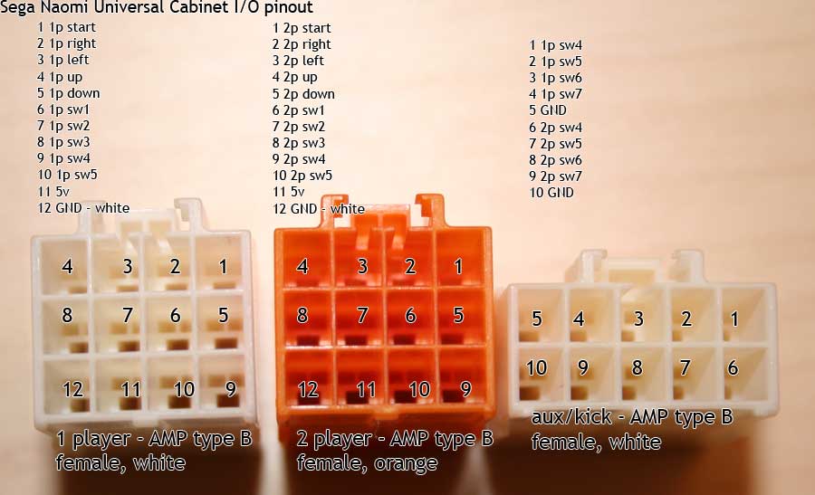
by-pass cable for test... use this image making bridge with a cable pin buttons

repeat by-pass all harness ... making bridge with a cable in CN3 60 pin direct buttons
use this scheme diagram from AGS site
http://triplemoonstar.brinkster.net/the ... ockid=1718
Digital Inputs (60pin JST RH connector)
---------------------------------------------------------
01 (+5V)
02 (+5V)
03 (+5V)
04 (+5V)
05 (+5V)
06 (+5V)
07 (+5V)
08 (+5V)
09 (GND)
10 (GND)
11 (GND)
12 (GND)
13 (GND)
14 (GND)
15 (GND)
16 NC
17 (1P Start)
18 (2P Start)
19 (1P Right)
20 (2P Right)
21 (1P Left)
22 (2P Left)
23 (1P Up)
24 (2P Up)
25 (1P Down)
26 (2P Down)
27 (1P SW1)
28 (2P SW1)
29 (1P SW2)
30 (2P SW2)
31 (1P SW3)
32 (2P SW3)
33 (1P SW4)
34 (2P SW4)
35 (1P SW5)
36 (2P SW5)
37 (1P SW6)
38 (2P SW6)
39 (1P SW7)
40 (2P SW7)
41 (1P Service)
42 (2P Service)
43 (Test Sw)
44 (Tilt Sw)
45 (Coin SW1)
46 (Coin SW2)
47 NC
48 NC
49 (Coin Meter 1)
50 (Coin Meter 2)
51 (Output 1)
52 (Output 2)
53 (Output 3)
54 (Output 4)
55 (Output 5)
56 (Output 6)
57 (+12V)
58 (+12V)
59 (+12V)
60 (+12V)
Posted: Wed May 05, 2010 5:19 pm
by OldFoo
Hi, thanks for the fast answer. I?ll try it.
Is it normal that the JST RH Connector isn?t prepared for all buttons right from the beginning? Is it a common problem that the last 2 buttons don?t work?
MFG
Posted: Wed May 05, 2010 5:40 pm
by OldFoo
Its quite common on these for 'just a couple or a few' buttons to stop working even though others are fine :smt010 i know from experience these I/O's are pretty fragile.
Posted: Wed May 05, 2010 6:04 pm
by OldFoo
Does that mean that I?have to buy a new I/O Unit eventually?
Posted: Wed May 05, 2010 8:59 pm
by OldFoo
If you can't diagnose the problems something else and want 6 buttons per player then looks very likely.
Posted: Thu May 06, 2010 9:00 am
by OldFoo
hi
can you post a pic from your extra harness? The pinout may be wrong...
