Chihiro at home
-
OldFoo
Chihiro at home
Whats up guys. Is there any alternative to playing Chihiro games in a dedicated cab? I'm thinking Outrun 2 specifically. Model 2/3 is pretty much impossible as far as drivers go, but I was hoping there may be a solution for Chihiro. Lack of space for a cab is the main problem.
-
OldFoo
Re: Chihiro at home
lordviper63 wrote:Whats up guys. Is there any alternative to playing Chihiro games in a dedicated cab? I'm thinking Outrun 2 specifically. Model 2/3 is pretty much impossible as far as drivers go, but I was hoping there may be a solution for Chihiro. Lack of space for a cab is the main problem.
Yeah, you can hack a Dreamcast or similar wheel and wire to a JVS I/O Board, and then hack an ATX PSU to power the JVS I/O and Chihiro.
You can do similar with pretty much all Driving games.
-
OldFoo
-
OldFoo
-
OldFoo
Re: Chihiro at home
AndyGeezer wrote:lordviper63 wrote:Whats up guys. Is there any alternative to playing Chihiro games in a dedicated cab? I'm thinking Outrun 2 specifically. Model 2/3 is pretty much impossible as far as drivers go, but I was hoping there may be a solution for Chihiro. Lack of space for a cab is the main problem.
Yeah, you can hack a Dreamcast or similar wheel and wire to a JVS I/O Board, and then hack an ATX PSU to power the JVS I/O and Chihiro.
You can do similar with pretty much all Driving games.
Wow thats very cool. I can hack the PSU no bother, I have done that before but what would the pin out be for the drivers.
Is it essentially a pad hack andy.
Cheers
Purplec
-
OldFoo
-
OldFoo
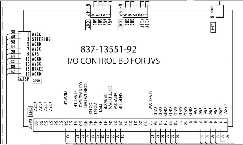
Well, the steering wheel is an analog control.
The pins marked 1,3 and 5 on CN26 on the I/O all connect to a 5k ohm potentiometer that is part of the steering wheel assembly. The AVCC line is a 5V output that connects to pin 1 on the potentiometer, the GND pin goes to pin 3. The STEERING pin connects to the slider/wiper pin (usually the middle one, pin 2) on the potentiometer. This way, the potentiometer provides an adjustable output voltage on the steering pin (ranging from near 0V to 5V) depending on the position of the potentiometer, which is read by the I/O. The potentiometer is actually nothing more than a variable resistor.
The pins marked 1,3 and 5 on CN26 on the I/O all connect to a 5k ohm potentiometer that is part of the steering wheel assembly. The AVCC line is a 5V output that connects to pin 1 on the potentiometer, the GND pin goes to pin 3. The STEERING pin connects to the slider/wiper pin (usually the middle one, pin 2) on the potentiometer. This way, the potentiometer provides an adjustable output voltage on the steering pin (ranging from near 0V to 5V) depending on the position of the potentiometer, which is read by the I/O. The potentiometer is actually nothing more than a variable resistor.
Last edited by OldFoo on Tue Aug 24, 2010 9:12 pm, edited 2 times in total.
-
OldFoo
-
OldFoo
purplec wrote:So
1,3,5 connect to the steering
7,9,11 conect to the acc
13,15,17 connect to the brake
all the above use pots I take it, would a dreamcast or similar console wheel use pots
Cheers
I edited my post above while you were replying
-
OldFoo