Posted this over at Killercabs, but thought it may be of use here as well, for those who haven't ventured over to the dark-side...
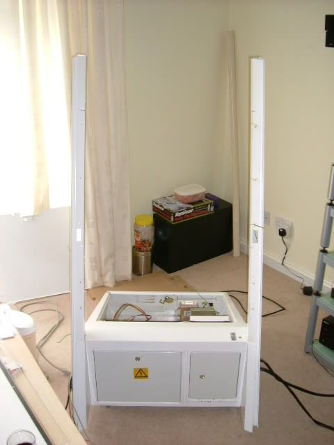
First you need is the base
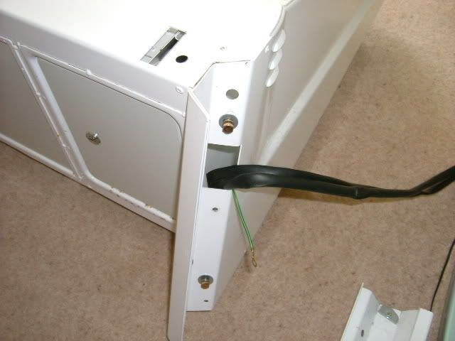
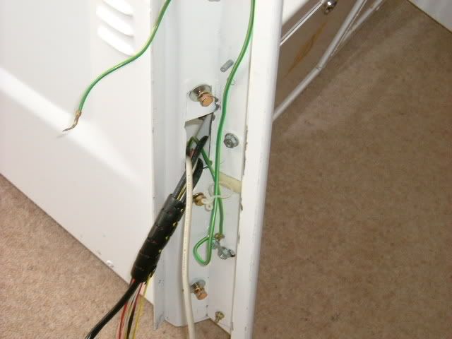
Pull the cables out of the holes either side of the base
Attach the legs (these have been chopped down!), making sure you remember to feed the cables through the holes.
You now should have something looking like this...
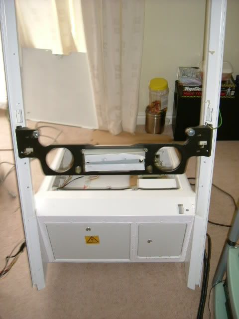
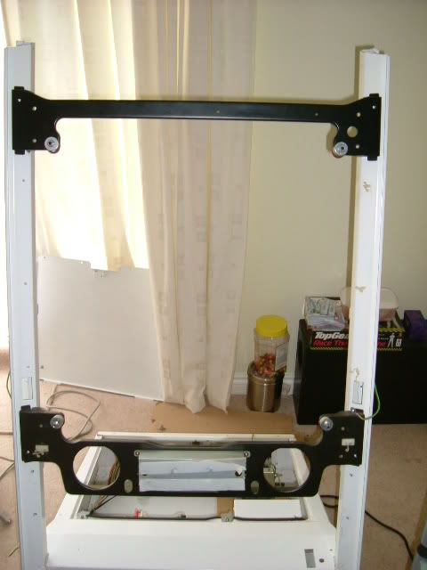
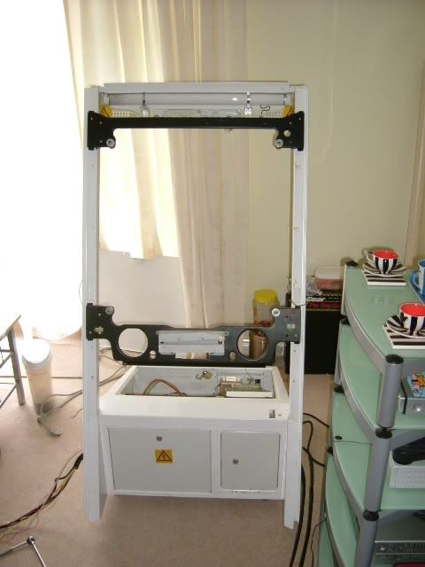
The next bit is to attach the horizontal bars, which double as the monitor support.
The legs have holes for fixing the bars to the legs, and also a small notch, which enables you to get the bars the
correct way up. The one with the speaker holes goes to the bottom.
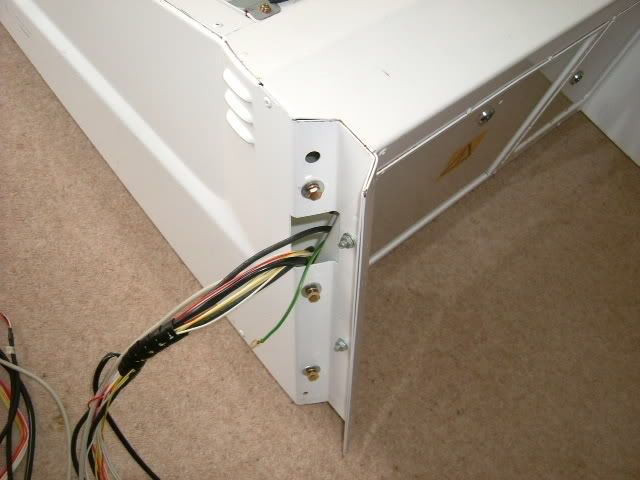
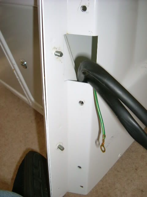
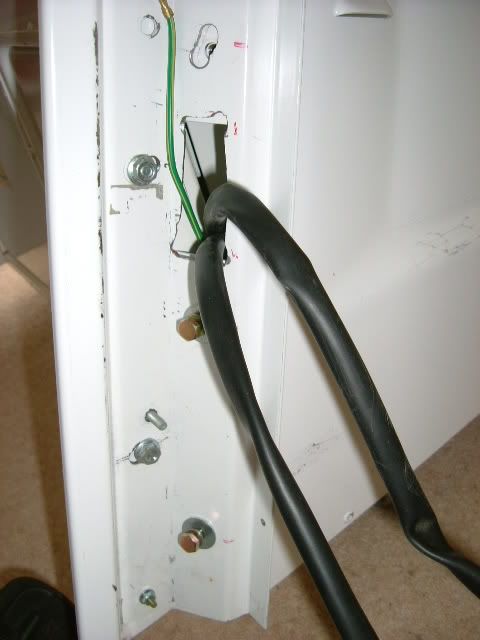
Attach the earth cables to the relevent points. (There should be a threaded bar near to where each cable finishes)
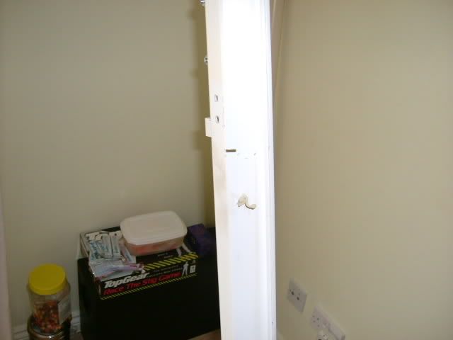
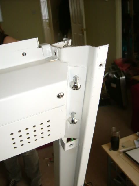
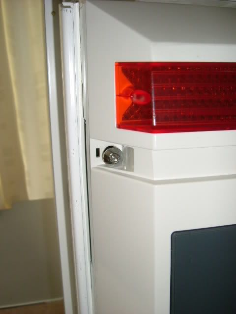
The light box attaches to the rear of the legs with 4 Torx bolts.
(These next images are in the wrong sequence. I put the CP on before putting the monitor in, but it is easier to fit the
monitor before the CP)
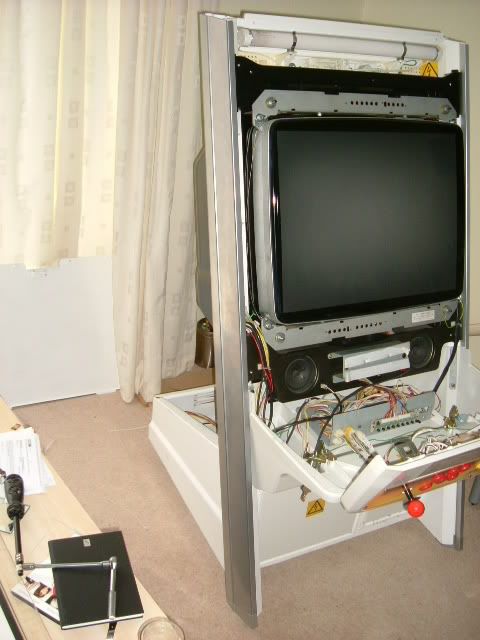
Take 1 monitor (tri-sync in this case)
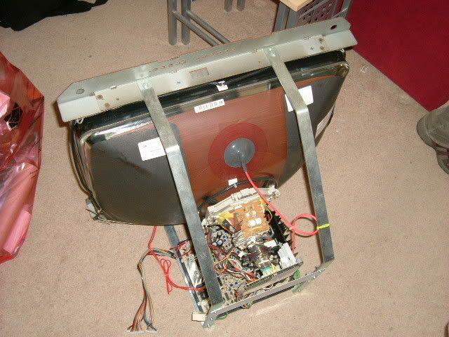
and by yourself (if you're strong) or with some help, lift the monitor onto the 4 white plastic washers on the horizontal
beams. Once it's there, it will happily sit while you get the washers & nuts fixed in place.
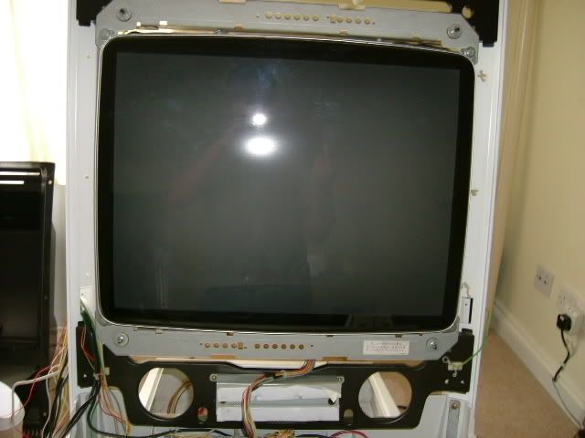
Feed the monitor remote cables to the front of the machine,
and attach the earth wires. Also get the power to the monitor from the cables on the right hand leg, and the VGA cable
should come out of the left hand side.
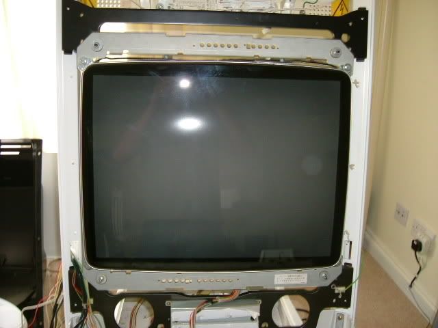
OK, now it's time to fit the CP.
Take you CP assembly
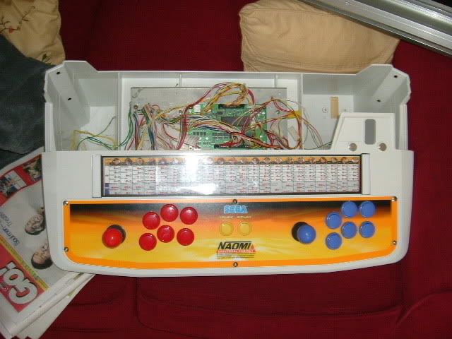
Line up the holes on either side
and attach to the frame with the 2 bolts & the brace bar
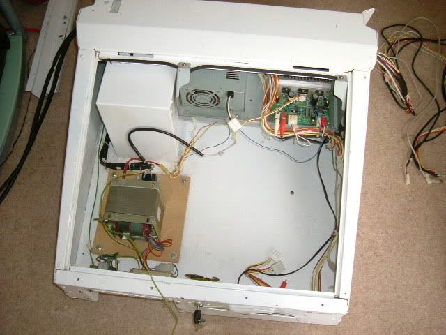
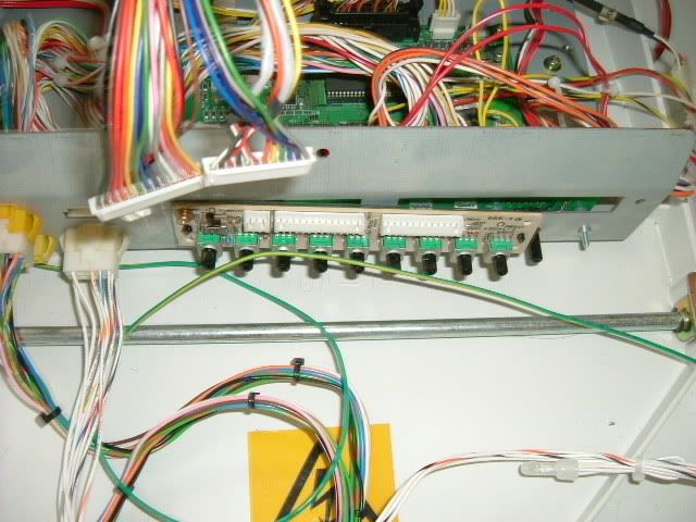
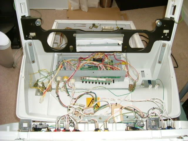
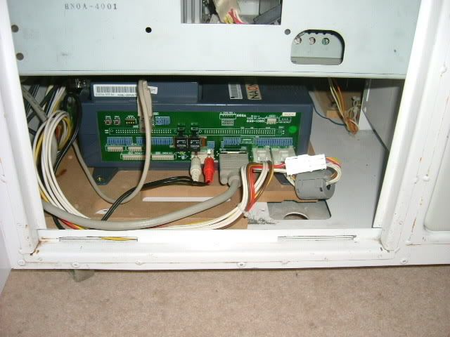
This piccy shows the I/O & all the CP cabling connected, as it was all in the CP assembly. You can see in the middle,
the remote board for my pentranic tri-sync. It's a simple case of finding the correct wires from the left leg, and
connecting them to the I/O.
Remember, this is your friend...
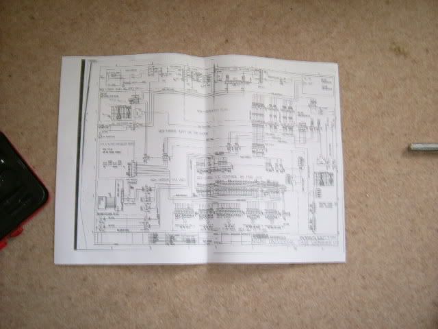
It's a fairly easy schematic to read, as it has the number of pins on each AMP U/P connector, and it's colour, and the
cable colours.
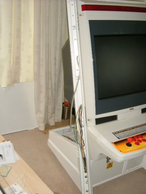
OK, this is when the cab starts to really take shape.
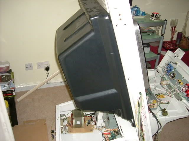
Grab the monitor rear cover & speaker housing. The housing should push-fit to the rear of the cab, and then be secured
in place with 6 Torx bolts.
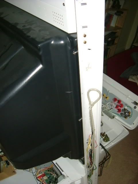
The speaker cables are colour-coded Red & White, and plug into the appropriate hole.

OK, lesson 2 - fit the leg covers before the cabinet front. Again piccys are a bit backwards as I learnt the hard way &
ended up taking the front off again!
Take a leg full of unsightly wiring
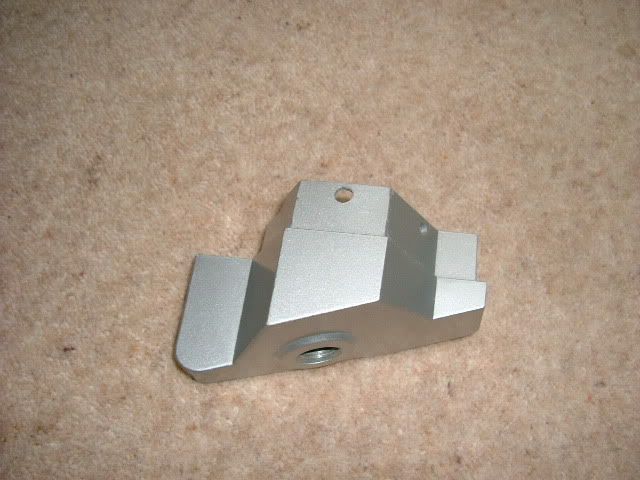
Take a foot
and if you're using them, add the stabilisers now, as it makes life easier (I forgot, so didn't bother)
Attach the foot with the screw
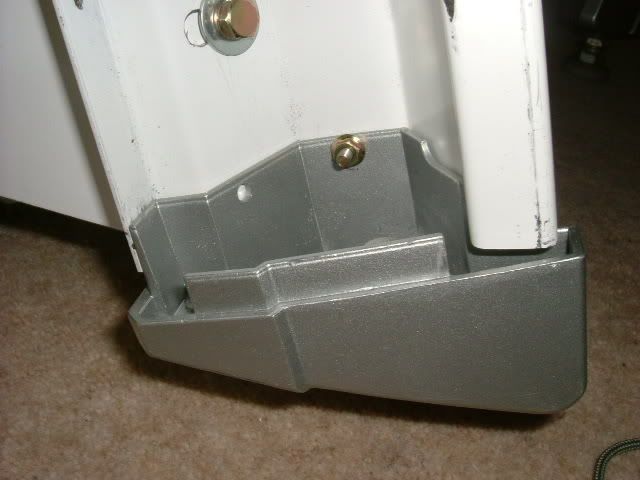
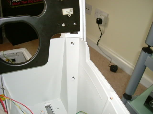
Attach the leg-cover. I had to slide mine from the top, but you may be able to clip it round the leg.
If you have them, put the leg tops on as well, and secure with a screw.
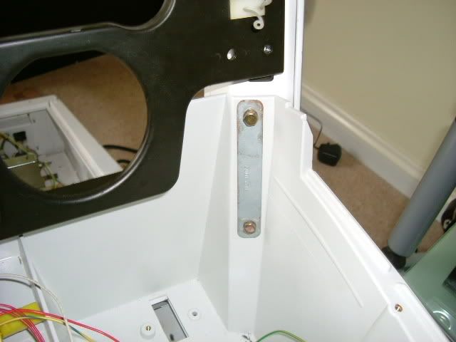
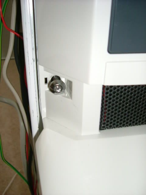
Right, take the monitor bezel/cab front assembly, and offer her up to the machine. There are 4 torx bolts to hold it to
the front (two at the top, and two at the bottom)
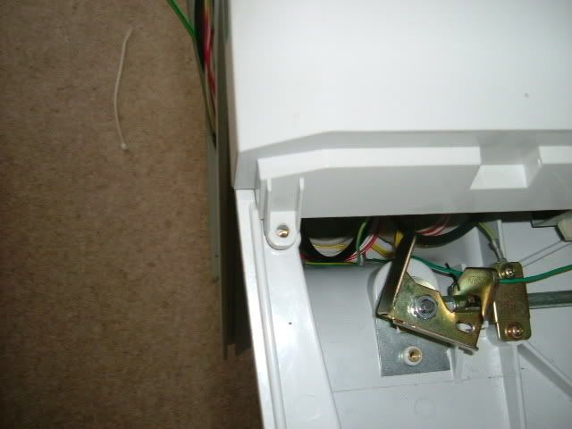
and two screws to secure it to the CP assembly
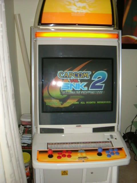
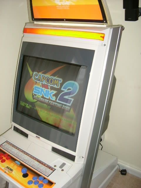
Add the gameing system of your choice (in this case a Naomi2 GD-ROM setup)
Attach the access hatch cover & the base top (securing it if you want). Put machine into it's final resting place.
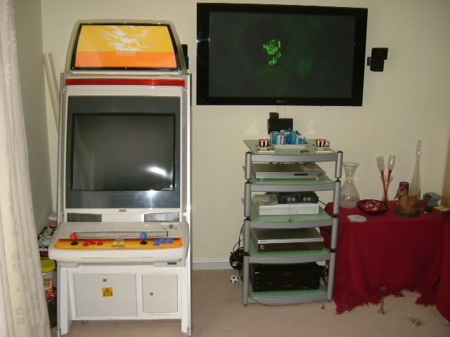
Bootup!